Introduction
Here is the idea. I want to make a PCB the size of a business card that you can play the game Snake on. I want to base the design on an Arduino using the Atmega 328 chip and I want the “display” to consist of a 6×6 LED matrix. I want to hand solder the entire PCB myself, and to make sure it does not get too thick, I am only going to use SMD components.
The next three sections below describe different aspects of the design. In them I explain my thought process and why I made certain decisions. The final section showcases the finished product. I also discuss things I would do differently if I were to make a project like this again.
What Is Snake?
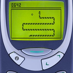
Snake is of course the old game that we all used to play on our mom’s Nokia 3310. However, if you do not know, the game consists of only two elements: one snake and one piece of food. Your job is to control the snake. It can move in the four directions: up, down, right and left. You eat the food by steering the snake to the spot where the food is. The goal of the game is to eat as much as possible, and every time you do, the snake gets longer. You lose the game if you cross path with yourself. Since you get longer each time you eat, the game gets progressively harder the more you eat.
Circuit
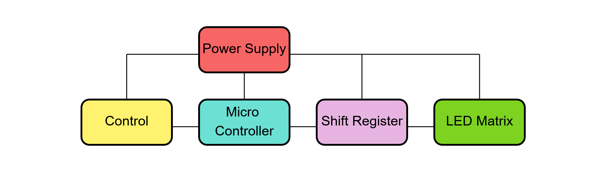
The circuit that is needed to make a functioning game is quite simple. It will consist of five parts which are shown schematically in the figure right below. Before presenting the entire circuit, the sections below aim to describe how all the parts function and what considerations were taken when designing their circuits.
Power Supply
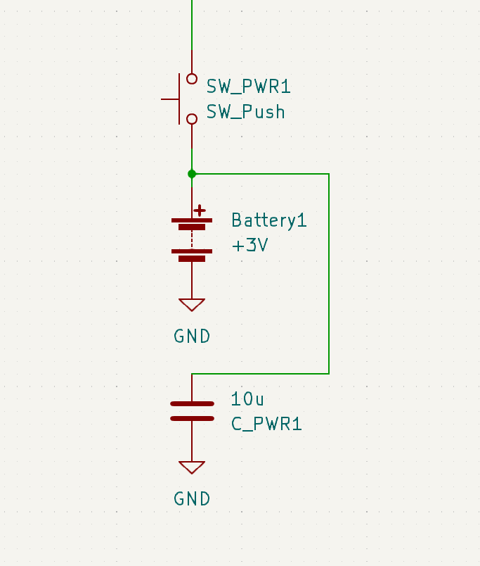
The green LEDs that will be used for the LED matrix needs 3V. The Atmega328 chip can happily run on 3V, so to keep the design cheap and easy we will run the circuit from a 3V battery. To make sure that the power is delivered clean we also add a capacitor. We cannot forget that we need to be able to turn off the circuit. This game is not meant to be played for an extended amount of time, but is more meant as a demonstration. The power button will therefore be a momentary switch that keeps the game running for as long as you hold down the switch. I decided to do it this way so that the game could not be left on by accident.
Control
To be able to actually play the game there has to be a way of controlling the snake. The snake can move in for directions: up, down, right and left. This can be achieved with either two or four buttons. With four buttons, each button can represent the direction of which you want the snake to go in. With two buttons, they can instead represent how you want to rotate the movement. One button will be for the clockwise rotation and one will be for the counterclockwise rotation. For example, if you are moving up and press the button for clockwise rotation, you will start to move to the right. However, if you are going down and press the same button you will start going to the left.
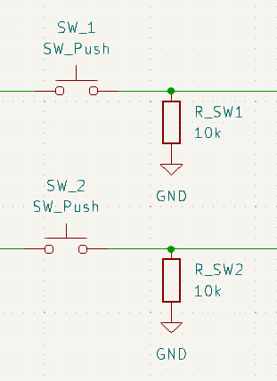
Four buttons are slightly easier to use since your button press is independent of the snake’s movement direction. Two buttons on the other hand, are easier and cheaper to implement. It can also be seen as part of the game to know which direction the snake is moving in. Therefore, I chose to use only two buttons.
The two buttons will be implemented using two momentary switches. Each button will also have a pull-down resistor so that the button presses can be registered by a micro controller.
Micro Controller
If we would attach an actual Arduino to the finished design, it would both get way too bulky and it would be unnecessarily expensive. However, basing the design on an Arduino is still a good idea since we can start with an Arduino and make sure the design works with one less variable. It also means we can use the Arduino programming language and IDE.
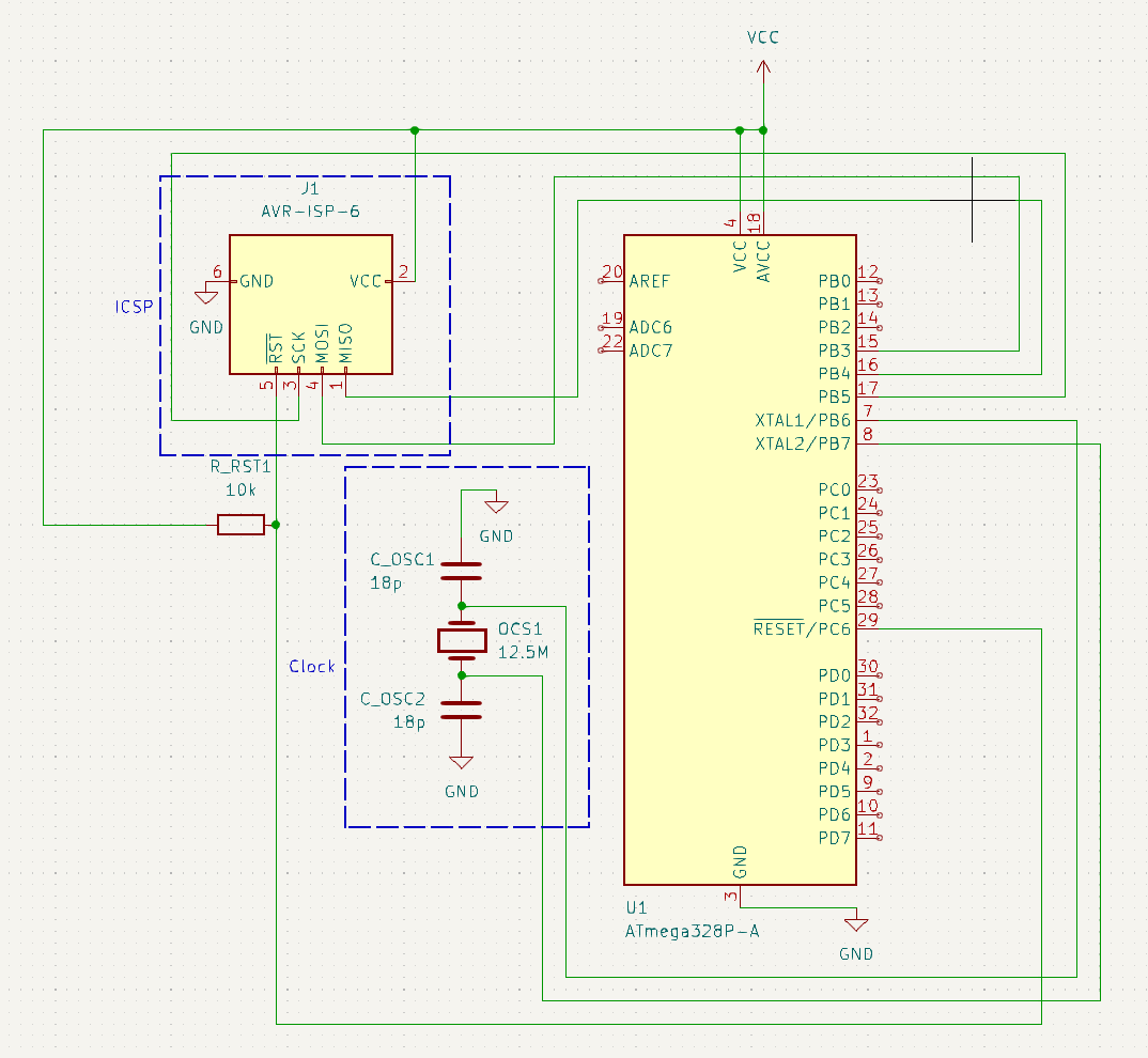
So, what we want to do is to remove everything from the Arduino Nano circuit except what is needed to run the Atmege328 micro controller. This allows us to integrate this simplified circuit directly on to the finished PCB instead of having the logic on a separate PCB, which would be the case if we were o use a full-blown Arduino.
As it turns out, not much is needed to run the Atmega328, all we need is a clock signal and power. However, we also need to be able to program the chip. So, we also need to connect the ICSP pins.
Shift Register
The atmega328 and therefore the Arduino has 14 digital pins. To run a 6×6 LED matrix, 12 pins are needed. We also need two buttons to be able to control the snake. Therefore exactly 14 pins are needed to run the game. However, three of the pins are needed for the ICSP header to be able to program the chip. So let us use a shift register for a better and more interesting design.
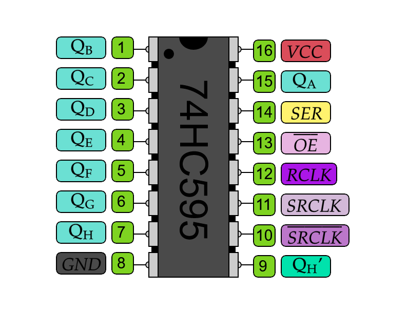
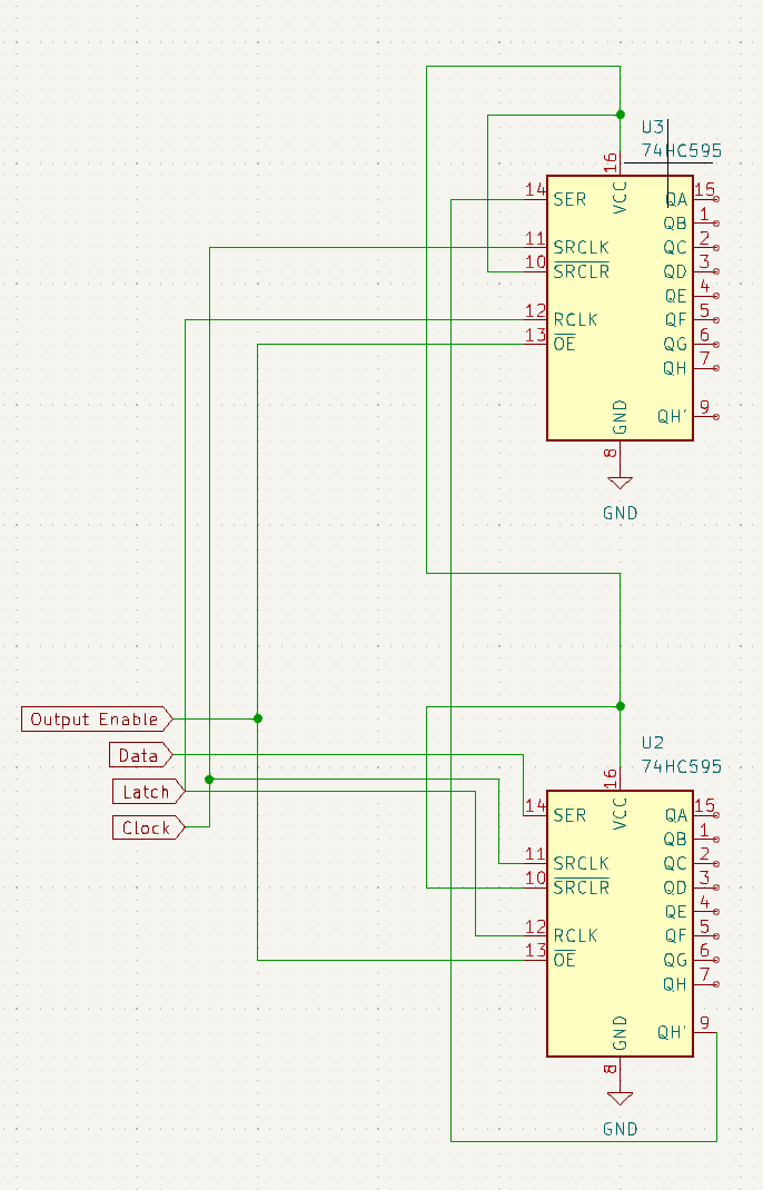
We will use two 74HC595 shift registers. By connecting QH‘ from the first shift register to the SER on the second one, they will act as one register with 16 outputs. Though not strictly necessary, we will also use the output enable pin. With this pin we can turn off the output of the shift register, so using a PWM signal we can dim the LED matrix if we feel that it is too bright.
What is shift register?
A shift register effectively gives you more digital pins by independently controlling a number of parallel pins on the shift register from three pins on the atmega328 chip. One pin needs to give a clock signal, connected to SRCLK. Serial data needs to be sent to SER and a latch signal needs to be sent to SRCLK.
A shift register works by having two registers inside. One register receives serial data by getting a 1 or a 0 every clock pulse. With every clock pulse the information of the register is also shifted one step, so that the newest binary data is stored in the last position and the oldest binary data is discarded. When this register is filled with the desired information, a latch signal is sent. The data will then be copied to the storage register. The storage register represents the output of the pins of the shift register. For example, if it has [0, 1, 1, 1, 1, 1, 1, 1], all Qx pins will be on except for QA.
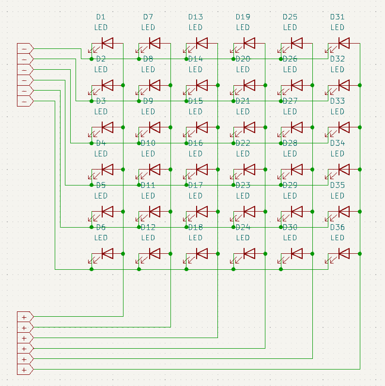
LED Matrix
With our two shift registers, the maximum size of our display is 8×8. However, I wanted the display to have as few LEDs as possible but still be a fun playable experience. There are two reasons for this: space and cost.
I decided that the beginning snake would have to be at least 2 units long, so that it would still look like a snake. I randomly decided that the display would at least have to be three times the length of the snake when the game starts. Which meant that my display would have to be 6×6. The matrix circuit was created by connecting all six anodes in one row together, and all six cathodes in one column together.
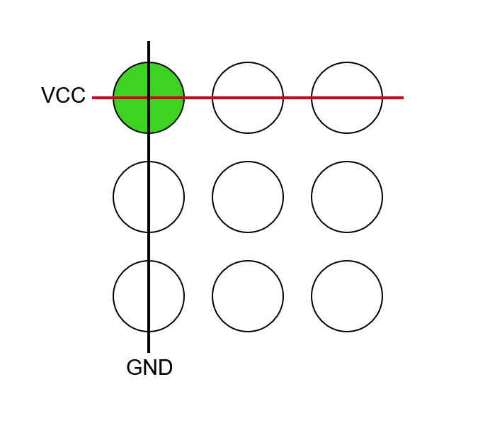
What is an LED matrix?
A matrix works by connecting all LED anodes in a row togehter and all LED cathodes in a column togehter. Now to turn on LED (1, 1) in an (n, m) matrix, you simply have to connect row 1 to VCC and column 1 to GND.
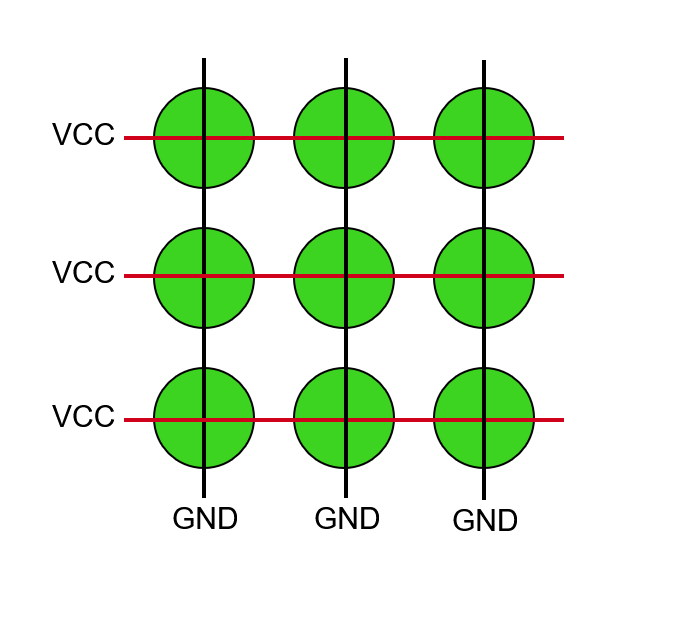
The keen eyed reader will notice a problem when you want to have many LEDs on at onece. Let us say you want to turn on the diagonal (1, 1), (2, 2) and (3,3). Then you will connect rows 1, 2 and 3 to VCC and columns 1, 2 and 3 to GND which will cause all nine LEDs to turn on.
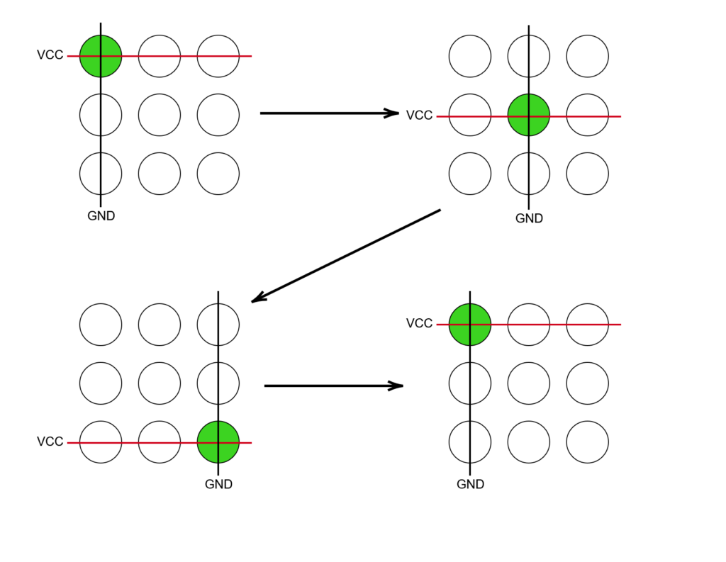
So how do we solve the problem of turning on multiple LEDs? We turn on one column at a time! This may seem strange at first, but if we switch between the columns fast enough it will look like all of them are on at the same time beauce of the slow response time of the human eye. So to turn on the diagonal we start by connecting row 1 to VCC and column 1 to GND. The next tick we connect row 2 to VCC and column 2 GND. The third tick we connect row 3 to VCC and column 3 to GND. The forth tick we go back to row 1 and column 1, and so on. With this method all LEDs in the matrix can be controlled independently without flickering, as long as the loop is fast enough.
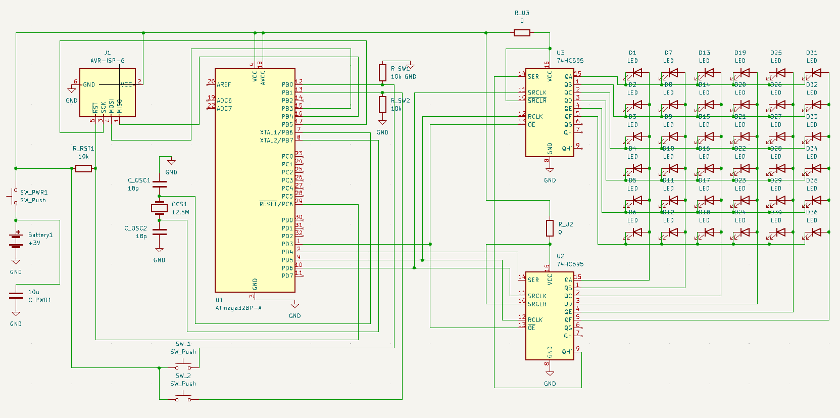
Full Curcuit
Connecting the five circuits from above gives us the final result.
PCB Layout
The first thing we need to decide is how many layers we want the PCB to be. The circuit is not complicated, or space restrained enough to merit more than two layers. Everything could have fit on one side, but it would have made the front look very crowded. Since making it dual sided was the same price as single sided, i chose dual sided.
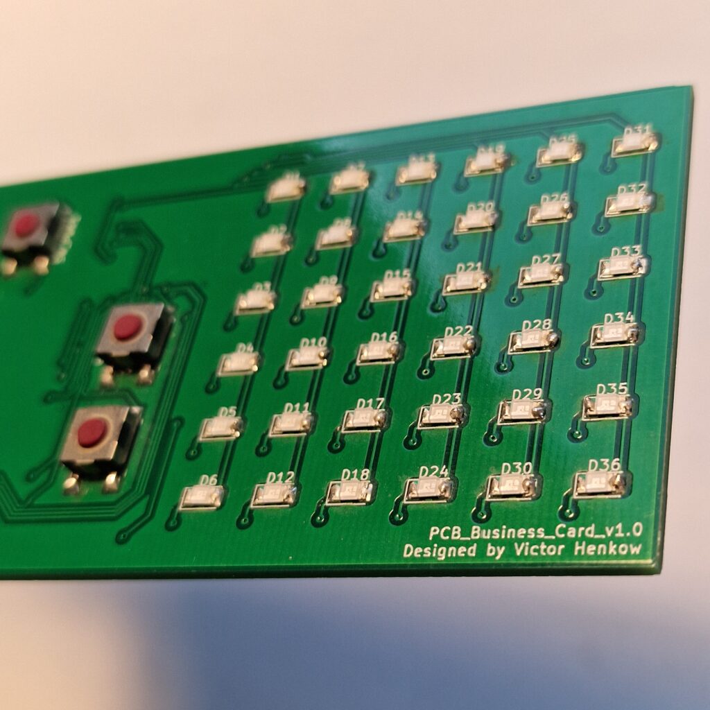
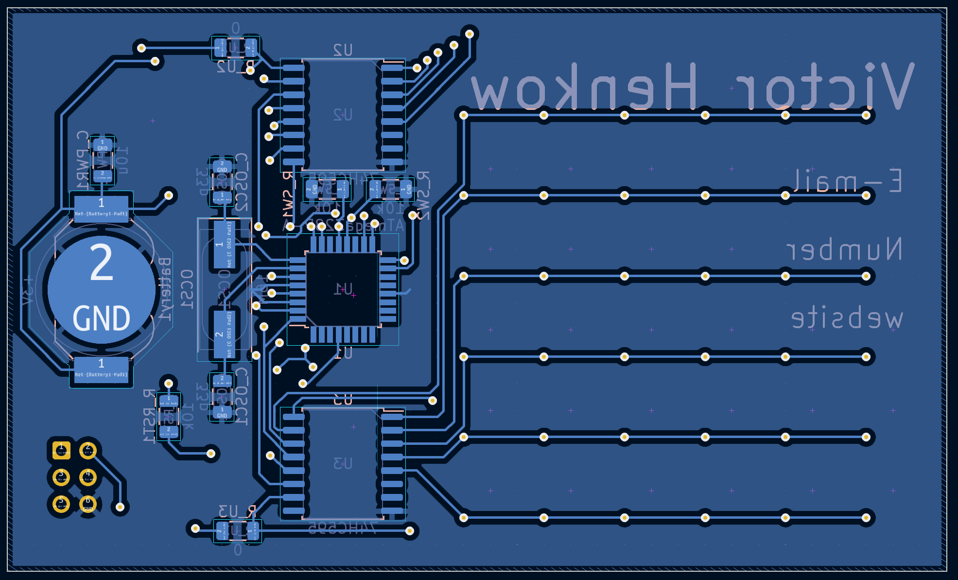
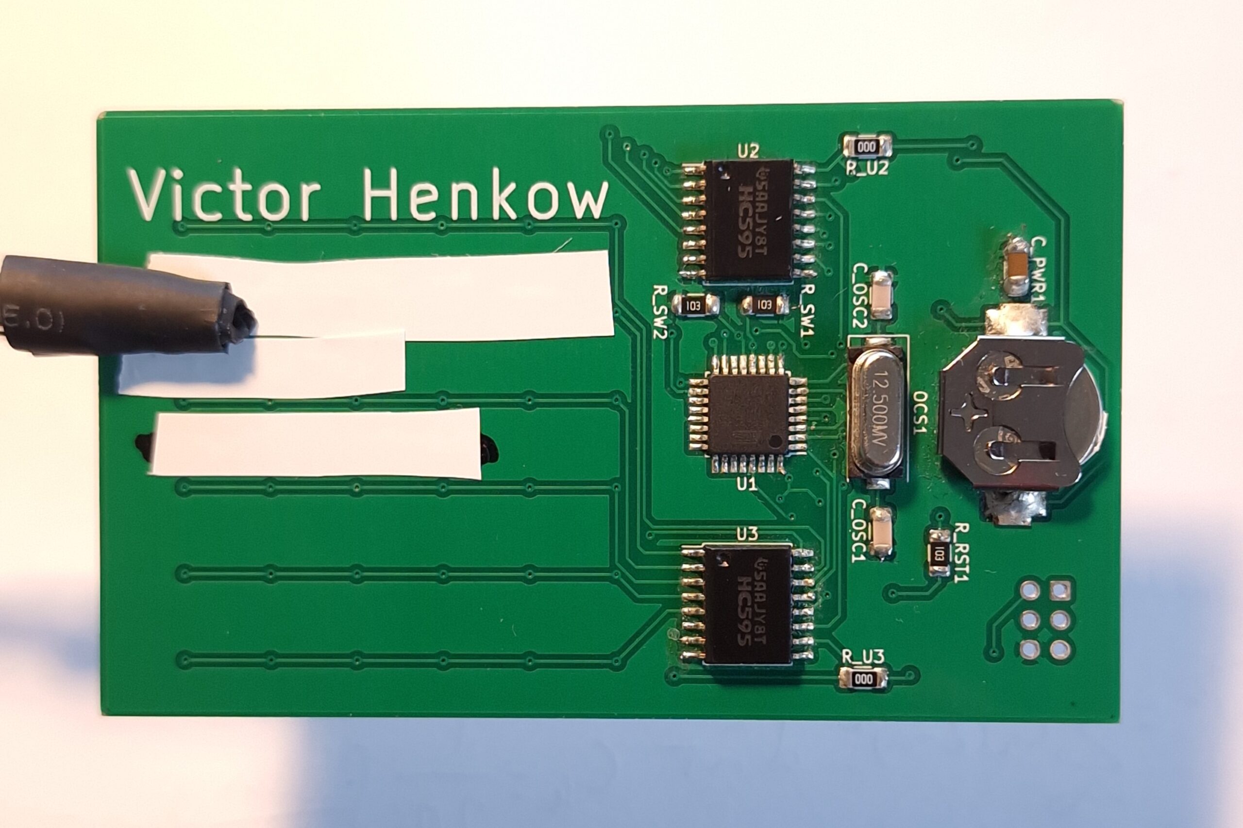
Backside
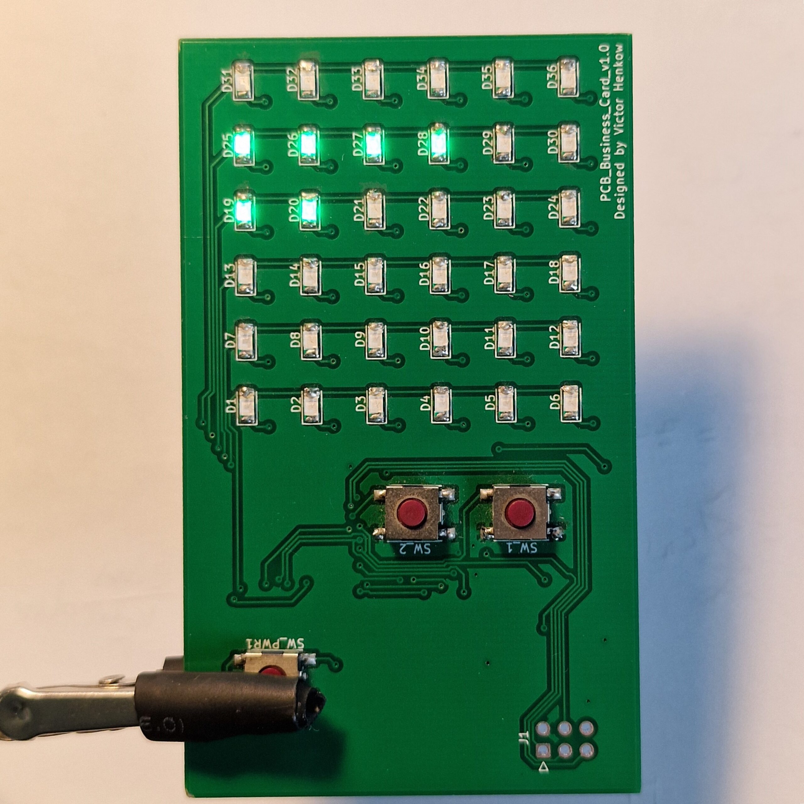
The back plane of the PCB is connected to GND. The back has all of the logic and the battery. Even though it is just logic, I still wanted it to look pleasing. Because of this I made sure to place the components as symmetrically as possible.
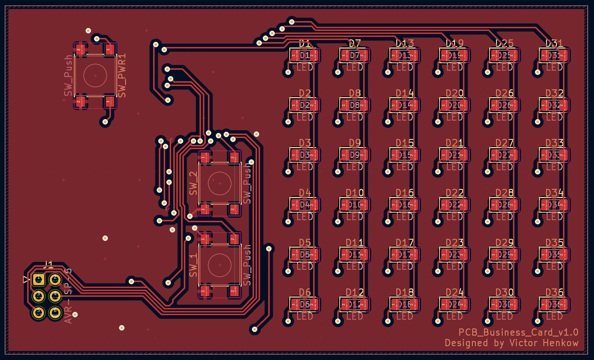
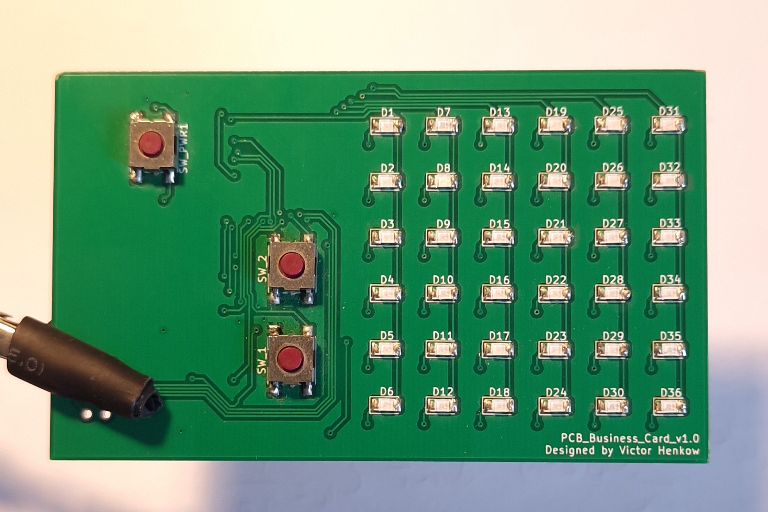
Frontside
The front of the PCB has the LED matrix and the buttons. I made sure to place the LEDs in a square with a spacing that would fill up the space good. I found that it was too cramped if you placed all buttons in a row. Therefor I placed the power button further down. I also made sure to place the buttons so you can hold the power button with your left thumb and control the snake with your right thumb.
To make it easier to draw the traces, I connected the front plane to VCC. In hindsight, I do not think this was a good idea though. In general, I think it is better to surround everything with ground to limit interference and protect sensitive electronics.
Program Code
I am not going to explain all of the code here. I am however going to explain the key aspects and the general thought process. The code is written using the Arduino language and is split up into three files. One is the main file handling the setup and loop functions. The two others handle the game logic and the LED matrix display respectively.
Main
The loop() function is the main loop of the program. Every iteration of the loop, the LED matrix is called to display the snake via the display(bool blink_food) function. blink_food determines if the food LED should be turned on or off. The food LED is set to blink at a steady pace using the blink variable and blink % 32 < 16.
void loop() {
  static byte blink = 0; // only used to calclulate when the food LED should be on or off

...

  // blinks the food
  if (blink % 32 < 16) {
    display(false);
  } else {
    display(true);
  }

  blink++; // will overflow but that is no problem
  speed_count++;
}If the game would progress every iteration, the snake would move way too fast. The speed of the game is determined using the two variables speed and speed_count. Every iteration of loop(), speed_count is increased. Once speed_count has reached the size of speed, the location of the snake is updated with the function step(bool right, bool left). The function returns if the snake has eaten. If it has, the speed of the game will increase by decreasing speed.
byte speed; // determines the speed of the game, lower is faster

void loop() {
  static byte speed_count = 0; // keeps track of when to progress the game

  if (speed_count >= speed) {
    bool eaten = step(right, left);

    if (eaten) {
      speed = speed * 0.92;
    }

    right = false;
    left = false;
    speed_count = 0;
  }

...

  speed_count++;
}We also need to detect if the snake should turn. To do this, we need to detect if any button has been pressed and released. If we only detect when the button is pressed, it will keep turning for as long as the button is held. Detecting when the button is released means that you need a new press every time the snake moves. I realized that doing it this way makes the snake much easier to control at higher game speeds.
void loop() {
  static bool right = false;
  static bool left = false;

  static bool buttonState1 = LOW;
  static bool buttonState2 = LOW;

...

  // This bit allows us to detect the realease of a button, which makes it easer to control
  if (buttonState1 == HIGH && digitalRead(sw1Pin) == LOW) {
    right = true;
    left = false;
  }
  if (buttonState2 == HIGH && digitalRead(sw2Pin) == LOW) {
    left = true;
    right = false;
  }
  buttonState1 = digitalRead(sw1Pin);
  buttonState2 = digitalRead(sw2Pin);

...Game
The main function for the game logic is the step() function. I have only included the case where we go in the right direction below, but the other four direction look similar. To understand step(), we first need to understand the array snake_pos. It saves the snake’s position as two coordinates which is their position in the LED matrix. It has a set length of 36, which is the maximum size of the snake. The standard value of the elements are 255, so all of the elements that does not have coordinates can be detected. The first element of the array is the head, the second is the one behind and so on.
step() works by first saving the head’s new position depending on which direction we are moving in. Once we have the new position of the head, we check if there is any food in that position. After that we move the snake with stepSnake(bool grow), where grow = true if the snake ate.
byte snake_pos[36][2];
byte direction; // the direction the snake is moving in; 0=right, 1=up, 2=left, 3=down

bool step(bool right, bool left) {

...

  byte head_u;
  byte head_v;

  // we want to move the head in the direction of movement, the rest of will just move one step forward
  // if the snake is at the edge, it should wrap around to the other side
  // we also need to check if the new head position is in the same as a food or as another part of the
  // snake. If we eat the snake needs to grow
  switch (direction) {
    // right
    case 0:
      head_u = snake_pos[0][0];
      if (snake_pos[0][1] < 5) {
        head_v = snake_pos[0][1] + 1;
      } else {
        head_v = 0;
      }
      break;

    ...

  }

  bool eaten = foodCollision(head_u, head_v);

  stepSnake(eaten);

...

} All that stepSnake() does is to move the elements in snake_pos by one index. Note that it does not update the new position of the head. The old head location at index 0 should be moved to 1, the second element at index 1 should be moved to 2, and so on. Doing this to all elements will increase the size of the snake by one. If the snake should not grow, the moving process should therefore stop one index early, which is controlled with the if(grow) statement.
void stepSnake(bool grow) {
  byte next[2];
  byte now[2];

  next[0] = snake_pos[0][0];
  next[1] = snake_pos[0][1];

  for (int i = 0; i < 36; i++) {
    now[0] = next[0];
    now[1] = next[1];
    next[0] = snake_pos[i + 1][0];
    next[1] = snake_pos[i + 1][1];

    if (grow) {
      if (now[0] == 255) {
        break;
      }
    } else if (next[0] == 255) {
        break;
    }

    snake_pos[i + 1][0] = now[0];
    snake_pos[i + 1][1] = now[1];
  }
}The last part of the step() function is to check if the new head position collides with the snake. If there is a collision, the game ends and restarts from the beginning. Otherwise, the position of the snake’s head is updated.
bool step(bool right, bool left) {

...

  if (snakeCollision(head_u, head_v)) {
    setupGame();
    eaten = false;
  } else {
    snake_pos[0][0] = head_u;
    snake_pos[0][1] = head_v;
    setSnakeHead(head_u, head_v);
  }

...

} LED Matrix
display() is the function responsible for translating the coordinates of the snake and the food to lit LEDs. Two 6×6 arrays, snake and food, are used to keep track of which LEDs should turn on. Each element if the arrays is a boolean true or false, corresponding to if the LED in that position should be on or not.
The state of the LEDs are controlled by two shift registers. The state of the pins on the shift registers are determined by the bits in the two variables reg1 and reg2. For example, reg1 = B00000001 sets all pins on shift register 1 to LOW except for pin 1 which is set to HIGH. reg1 = B11111110 on the other hand, sets all pins to HIGH except for pin 1 which is set to LOW.
As explained in the Circuit section. The LEDs has to be turned on one column at a time. This is done by stepping through, connecting only one pin at a time to ground on shift register 2. The other pins cannot be left floating so they are set to HIGH, which turns off the LEDs connected to those pins. The pins on shift register 1 is set to HIGH depending on the values in food and snake, and the value of blink_food.
bool snake[6][6]; // Where the snake is on the LED matrix
bool food[6][6];  // where the food is on the LED matrix

void display(bool blink_food) {

  for (int j = 0; j<6; j++) {
    for (int i = 0; i<6; i++) {
      byte reg1 = B0;
      if (snake[j][i]) {
        bitSet(reg1, 5 - j); // sets the bit if the LED in the specific row should be on
      }

      if (blink_food) {
        if (food[j][i]) {
          bitSet(reg1, 5 - j);
        }
      }

      // to turn off the LED, give high to both shift registers
      byte reg2 = B11111111;
      bitClear(reg2, i); // cycles connecting the column to ground

      ...

    }
  }
}Finished Game
Overall, the end result is just what I wanted. The game plays like I wanted, and I think the PCB looks aesthetically nice. Improvements can of course be made both to the circuit and to the code, but for a simple project I feel satisfied with the result.
I did make one mistake however, which I am a little bit salty about. Before designing the circuit board, I never tested the circuit with the battery I planned to use. I only tested it with my bench power supply. It turns out, the tiny battery I used cannot support the current needed to run the LEDs. It is possible to still make the board work by putting two batteries on top of each other in the battery holder. Since the rim of the battery is live, the bottom battery has to be isolated from the holder with some electrical tape. This puts the two batteries in series, which increases the voltage. Technically, this makes the output voltage too high for the LEDs, but at least it works.
There are also other minor things I would change if I were to do something similar again. Like I already discussed, the first thing I would change is to connect both sides to GND, not the front to VCC. I have not noticed any problems with it, but I feel like it is always good to design things properly.
Note! The slight flickering that appears in the video is not there in real life. It is only there because of the camera. It is the same as when you film an old CRT TV.
There are two aesthetic changes I would make. I would make sure to write below the buttons what they are used for. Maybe I would even write a short description of the game in the space left over. I also feel like the corners of the PCB are a bit sharp. If I were to make a project with a PCB without a case like this again, I would make sure to make the corners rounded.
If you want to look further into the design, the KiCad files and the program code can be found on Github.